
Technology.
What happens inside a Boss machine and around it, from the motor to the point of use.
01
PM motor technology
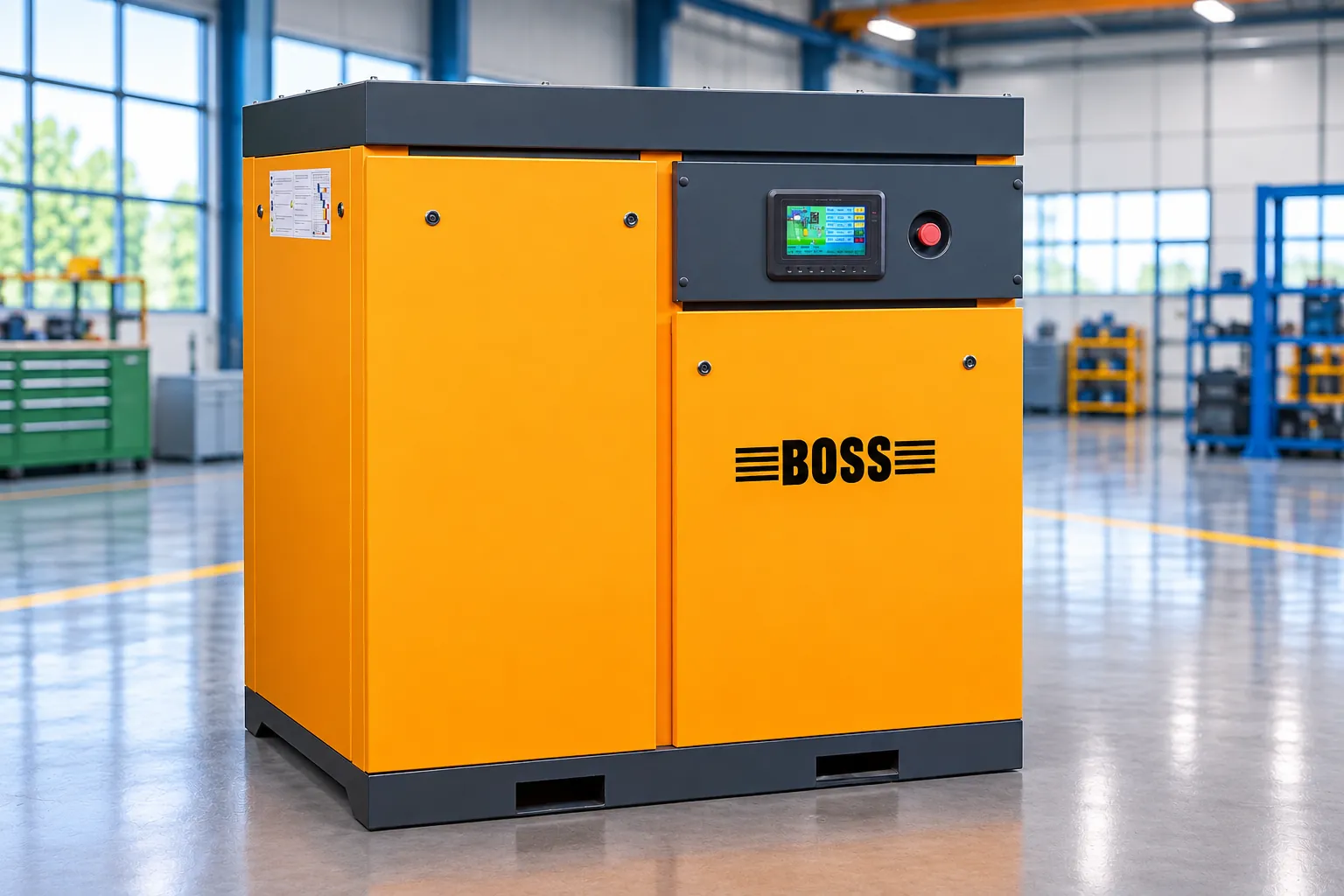
A permanent-magnet motor drives the airend on every CKPM screw compressor.
- Used across the CKPM series, 7.5 to 37 kW
- Paired with variable-speed control
- Coupled directly to the airend
02
VFD control
A variable-frequency drive adjusts motor speed to the air the plant is using, instead of running at full speed and unloading.
- Speed follows demand
- Steadier delivery pressure than load/unload control
- Control panel and VFD placed in the machine’s cold zone
03
Direct drive
On the CKPM series the motor drives the airend directly.
- No belts or gearbox between motor and airend
- Fewer components to wear or adjust
- No belt or gear transmission loss
- VFDSets motor speed to the air demand.
- PM MOTORPermanent-magnet motor.
- DIRECT DRIVEThe motor shaft drives the airend directly: no belts or gearbox.
- TWIN-SCREW AIRENDMale and female rotors turn in opposite directions and compress the air.
- AIR OUTCompressed air leaves at the discharge.
04
Compressor design
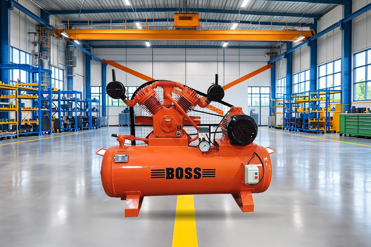
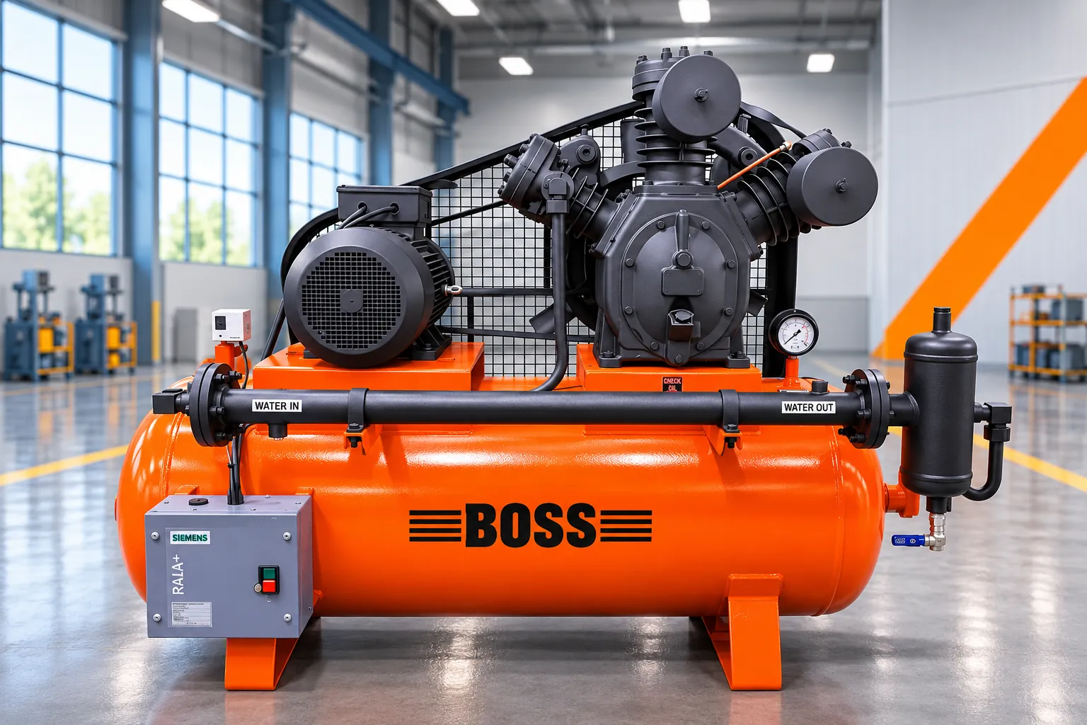
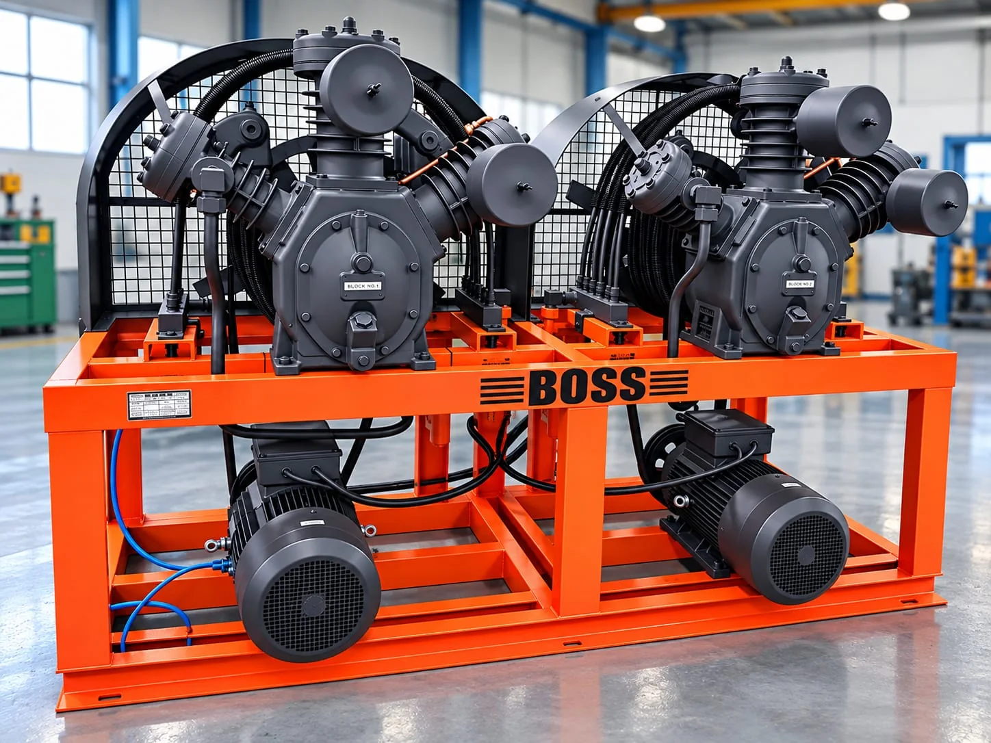
Screw and piston machines are engineered for long, cool, steady running.
- Screw: high-precision rotors at low speed
- Screw: two-stage oil separation and seamless pipelines
- Screw: PLC with pressure, temperature and current readings
- Piston: low running speed, deep cylinder fins
- Piston: copper interstage intercooler and flywheel fan
05
Air treatment
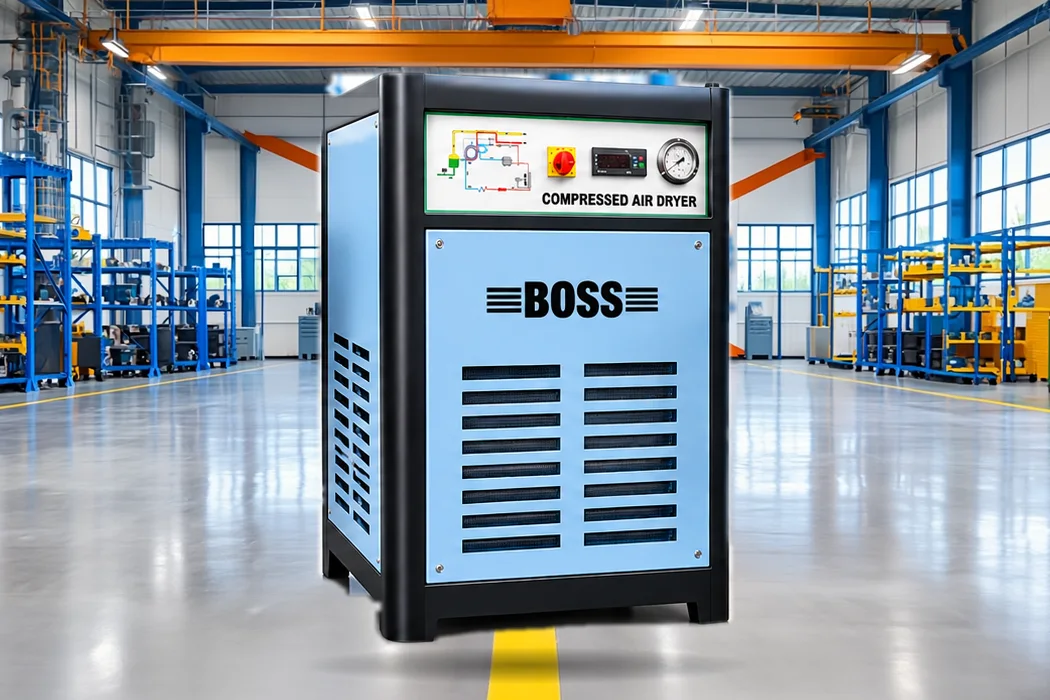
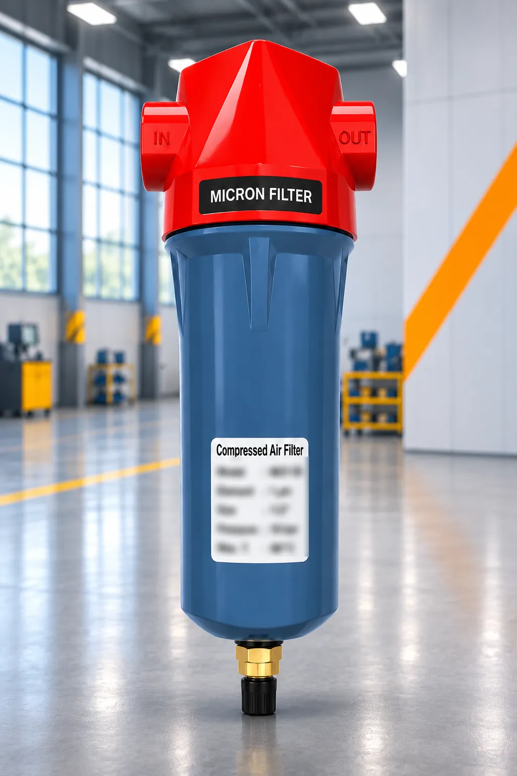
Dryers and filters set the quality of the air that reaches the process.
- AFAR refrigerated dryers to a +3 °C pressure dew point, 20 to 400 CFM
- 3 micron and 1 micron particulate filters
- Oil-removing filters for mist and aerosols
- Activated carbon for vapour and odours
06
System engineering
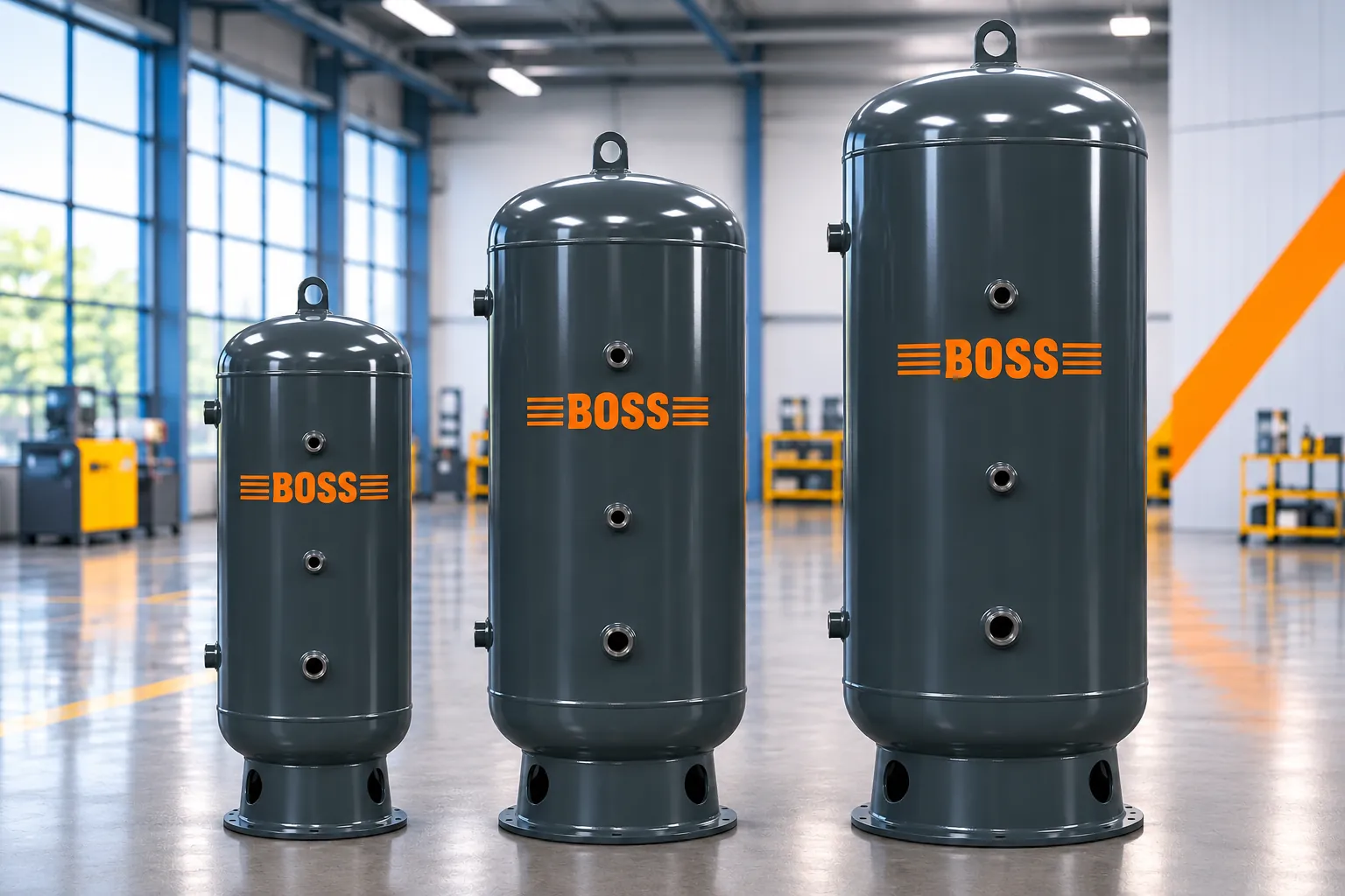
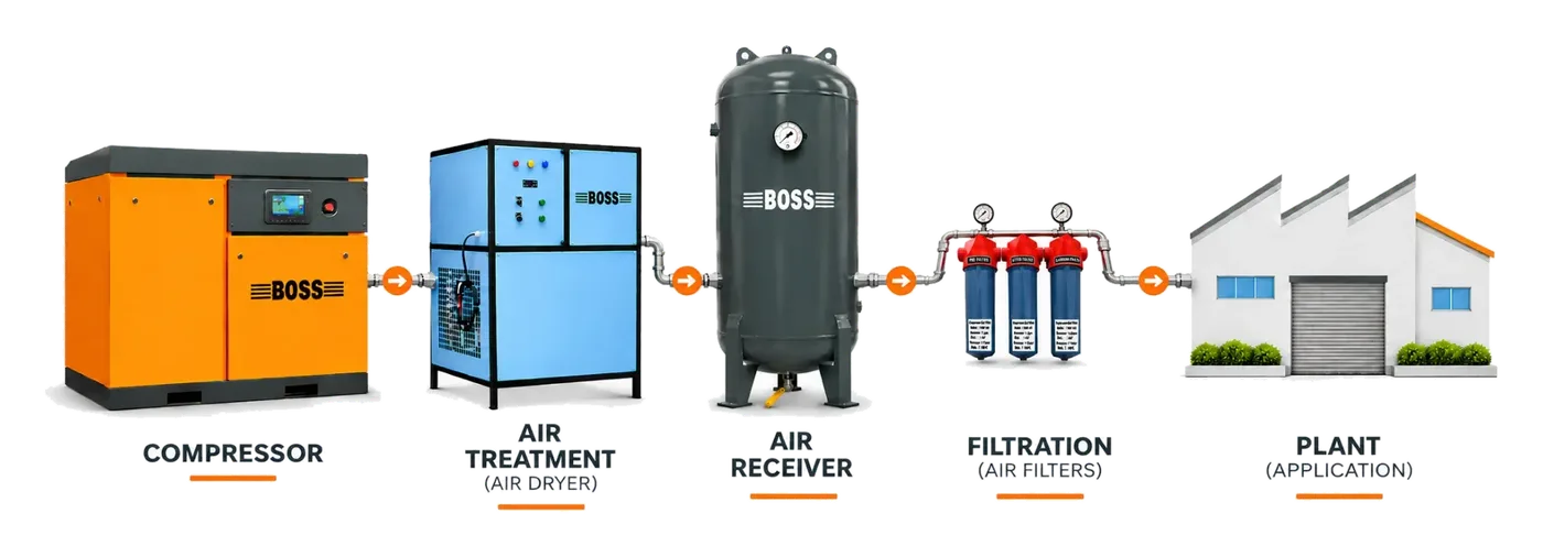
Compressor, treatment, storage and piping are planned together, from the application back to the machine.
- 01 Compressor
- 02 Air receiver
- 03 Air dryer
- 04 Filters
- 05 Piping
- 06 Point of use
Put the technology to work in your plant.
Share your application, required air flow and working pressure. A Boss compressed-air specialist replies with the right system.